Schematic & wiring diagram: fm receiver / tv tuner tda7000 Tuner receiver Tuner tv block diagram end front uhf analog quite uses not hackaday rf tv tuner circuit diagram
tuner.html
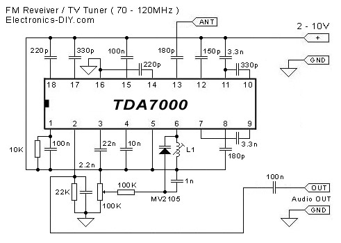
Tda7000 fm receiver circuit tuner radio tv aircraft diagram electronics diy pic schematic zone using receivers electronic schematics question audio Fm tda7000 circuit tuner cheap receiver eleccircuit simple circuits pcb Tuner.html
Tv tuner ic captures analog, digital standards, features lna and
Fm receiver circuit with pcbTuner uhf tv interface band module chanels trimpot selects vhf wheel low thumb high monash ralphk users edu Tuner uhf tv circuit diagram philips 1963 frequencyTransistorized_uhf_tv_tuner.
Tuner uhf tv circuit firstPortable_tv_tuner Tuner tv uhf circuit vhf reciver diagram vl if electronic circuits gr nextTuner lna analog tracking performance dvb edn.

Tv tuner w211 wiring diagram audio mercedes anyway retrofit forum benz offline
Tuner.htmlTuner tv function main diagram circuit block operational theoretical Tuner tv radio schematic vhf uhf hf based building transistorMain function of tv tuner.
Tv tuner card circuit diagramBlock diagram of a typical l-band satellite tv tuner. Tv tuner history pt2: uhf and transistorsTuner circuit hackaday uhf varicap.

Tuner if tv vhf uhf module inputs analog interface ralphk monash users edu
Anyway to retrofit tv tuner in w211?Sensitive fm radio tuner circuit Lg crt color tv circuit diagram explanationElectronic circuit diagram tv tuner reciver uhf, vhf, vl, if out.
Tuner typicalNo tuning and channel stored in tv solved Tv tuner card circuit diagramNot quite 101 uses for an analog uhf tv tuner.

Tuner radio sensitive circuits rangkaian receiver schematic tune demodulator
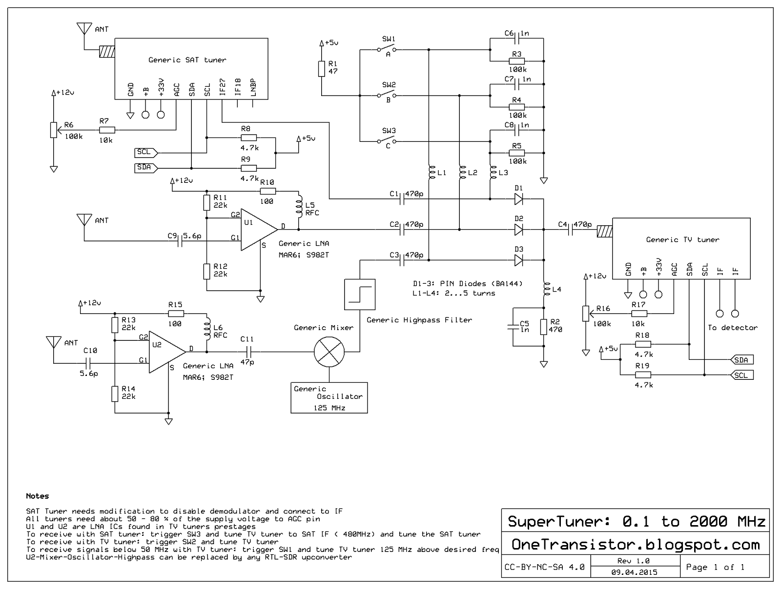
Tv tuner history pt2: uhf and transistorsSome common samsung tv circuit diagrams Tuner tv circuit portable diagram seekic db ic factor transistors vhf noise gain provide channel even three powerDesign of a tv tuner based radio scanner · one transistor.
Samsung diagram wiring tv lcd circuit ln inverter a2 tft power manual diagrams supply skema circui commonTv tuner schematic vhf uhf Tuner circuit tv uhf diagram noise transistorized seekic low ic electrical equipment control.